Ford Focus RS Forum banner

Headlight connector wiring and connector

35K views 21 replies 7 participants last post by  RSMex  
Sorry if I am clueless but is that how it really works? That would mean all of the turn signal bulbs for a side are in series?Then one failed bulb kills the entire side front and rear? That does not sound right? I am curious because I have the resistors wired into my rear signals but also could not see my way to doing it again for the much trickier front solution.
Why don't you add the resistor to the tail lamps? It doesn't matter where it is located as long as total resistance is enough to slow the flashing. I think the relay can be replaced with one that is meant for LED's making the whole job easier. But I haven't personally looked any up.

Sent from my Pixel XL using Tapatalk
 
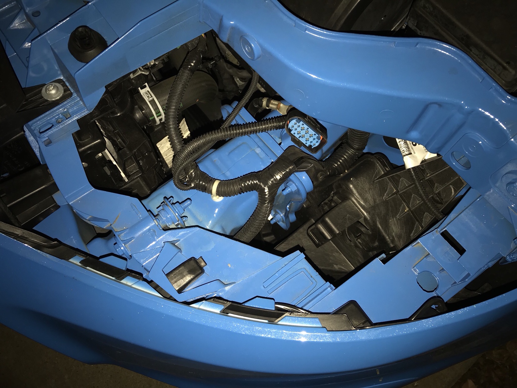
I have bought a set of replacement LEDs from SuperBrightLEDs as suggested in this thread: http://www.focusrs.org/forum/32-focus-rs-lighting/55385-led-bulbs-budget.html. Since my RS hyperflashes with these bulbs installed, I also bought a load resistor kit. However, it looks like I would need to tap into the wiring harness that connects to the headlight since none of the wiring is exposed on the outside of the headlight (unlike the tail lights). All the wiring for each bulb socket are on the inside of the headlight housing and it does not appear to be feasible to install the load resistors inside the headlights without disassembling the headlight.

Image


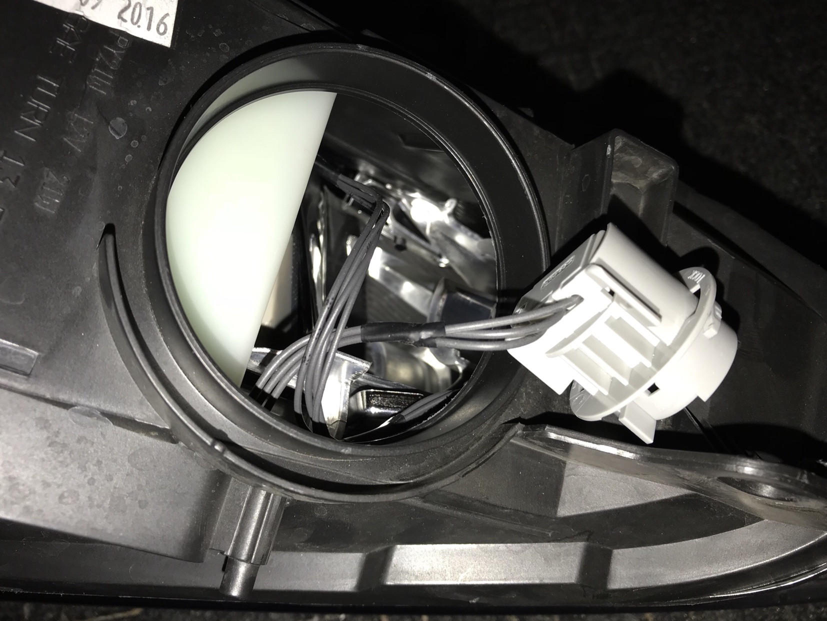
Has anyone been able to track down the wiring diagram for the headlight? Also, does anyone happen to know what kind of connector is used for the headlights? Another idea I’m considering is that if I can buy the connectors, I can make an extension of the harness that has the load resistors tapped to avoid modifying the factory wiring harness entirely.

Image
Does this help - unfortunately no part numbers in service manual
 
I think I understand your question. Assuming that the resistance measurement is for the fronts and rears all together, you should be able to install another set of resistors in the rear where there is room instead of the front. But you are asking how to get 6ohm + 6 omh = 12 ohm = serial connections, versus 6 ohm + 6 ohm = 3 ohms for parallel connection. So you would want the resistors set up with respect to each other in series but the two of them together in parallel with the rear bulbs. So, step by step, (i) R#1 has one wire patched into one of the bulb wires, (2) R#1 second wire connected to one wire on R#2 ( in series with R#1), and (3) remaining wire on R#2 connected back to other bulb wire so the set of resistors is in parallel with the bulb. Should give 12 ohms on each side for each bulb circuit. God I am stale on my old VIR calcs but I think that is what you are asking?


I think I’m not really clear on what the issue is. My question was whether I should mount a second set of resistors on the rear tail light circuits to account for replacing the front turn signals with LEDs. The documentation from SuperBrightLEDs says that one resistor is needed for each LED turn signal bulb and this four would be needed if both sets of front and rear bulbs are replaced.

The load resistors from both DD and SuperBrightLEDs are rated as 50 W, 6 Ohm. If I understand correctly, the 50 W rating just means that the maximum amount of power the resistors are rated to be able to take is 50 W. The resistance is what matters in terms of whether the resistor can compensate for the lower resistance of the LED bulbs compared to the filament bulbs. In this case, the two 6 Ohm resistors from the two resistors I already installed are enough to prevent hyper-flashing for the rear turn signals but are not sufficient to compensate for replacing the front turn signal bulbs with LEDs.

Is my understanding of this correct? If so, the point I want to clarify is that if I install a second resistor on each tail light turn signal circuit, should that resistor also be installed on a parallel circuit relative to the bulb since the first resistor is also parallel with the bulb?


Sent from my iPhone using Tapatalk Pro
 
I hope someone with actual knowledge of the RS wiring can provide an answer. It's exactly what I did not understand from earlier comments on this thread re the fronts and rears are on the same circuit. The idea that adding more resistors to the rear wiring solves the problem of the car seeing lower resistance from the LEDs suggests they would need to be in series or you would not get a higher overall resistance on the circuit? But, it just does not make any sense to me that it would be wired that way or a front bulb blowing out would take out the rear as well on that side if they are in series. It would, like wiring in your home, make sense for each bulb to be in parallel so they function independently. If that is the case, then adding more resistors to the rear set alone (whether added in serial or parallel with each bulb as described in prior post) should do nothing to stop the front hyperblink. But it would make sense per the directions you have that each bulb needs it's own parallel wired resistor? Help me out here professionals, I am relying on 20 year out of date electronics design coursework and have no idea if I am thinking correctly about this?
Thanks for the explanation. To be more clear, what I am wondering about is whether I need 6 Ohm + 6 Ohm = 3 Ohm (parallel) or whether I actually need 12 Ohms via the two resistors wired in serial. Based on the documentation included with my load resistors, the resistors are installed in parallel to the bulb for both the front and the rear, which leads me to believe that the resistors should be in parallel with each other than serial, but that is what I am not sure about.

Edit: here are the instructions from SuperBrightLEDs:

Image
Q