Ford Focus RS Forum banner

Focus RSE - SE or ST to RS swap with AWD

66K views 114 replies 30 participants last post by  crashcourse460  
#1 · (Edited)
Having done this kind if thing with various Impreza to STI models over the years, I thought I'd try it out with the Focus. I've seen lots of speculation on the plausibly and difficulty, so it's time to find out for sure.

Donor car, 2017 RS, appears to have taken out a moose or some other large hairy object, roof mostly sheared off.

Swap car, 2013 Focus SE. Basic, manual, with a sunroof.

I'll be changing out everything to the bare shell, and moving over the RS strengthening plates, missing captive nuts, and other little details.

I know it can be done, but let's see just how hard it is to do.
 

Attachments

#32 ·
Because if I ever wanted to reshell the car it would make it much easier, given that you can't buy those individual parts. A bit of an odd reason I know, but this will show a useful feature I was able to integrate.

Ever since discovering the secret of the structural foam, I've been thinking how best to incorporate the intended strengthening into the SE, without cutting open the frame rail. Looking at the design of the two boxed sections, amount and location of the spot welds, lateral movement was the only gain this modification provided. So, I made my own lateral braces.

Two triangular brackets extending from the rails at the boxed section into the floor. That on it's own is pretty good. Then I thought, well if we have the upper brace and lions foot parts bolted in, I could integrate all 3 support systems into one extremely solid brace.

I positioned them so the vertical structure of the triangles would interface with the same vertical structure above, and then bolt them together. Now, I really don't know if this is neccessary, a part of me feels even the rail is plenty strong enough as is, yet here we are.

Now that's all sorted, time to attach the flat floor. Both surfaces cleaned up with rough grit, and a bead of panel bond on either side which is then spread around. This stuff costs about $80, and the dual barrel gun is even more. Very useful though and mixes automatically! One that's all laid out, 50 rivets get put it - after which I seriously considered buying a powered rivet gun.

Floor brace and the lions get the same treatment of panel bond, but instead of rivets a series of m6 and m8 bolts. Some of which go directly into the triangles at the bottom, others go into the frame rail weld seams.

Definitely more complicated than necessary. The final result should actually be more rigid than an real RS, so that's something.
 

Attachments

#33 ·
Rear floor is sorted out, but there is still missing mount points for the gas tank and driveshaft. I decided to make captive nuts, because why not, but I suppose you could use speed nuts or drill a hole from the top if you lacked a welder.

Lining up the front driveshaft bracket confirms what I expected. The mount holes are there but lack the threads. Same situation for the rear mount, and the one missing gas tank mount. Circled in orange are the 5 captive nuts needed to be added.

The method I used was to obtain some large flanged nuts (M8), drill two holes on either side of the hole, and then weld them to it. Takes a bit of snaking, but all the holes had nearby access points large enough to get them inside.

In addition, and not strictly neccessary, I added the two captive bolts which hold the fuel filter below the RH forward gas tank strap. There is also one large hole needed under the rear seats for the LH fuel tank level sender. For whatever reason, there is also the addition of a sort of plastic bumper or protector that goes on the crossmember just behind the tank. It doesn't actually contact the tank at all, so not really sure what the purpose is. I marked and drilled the holes just in case. There is also a short stud on the SE in this area I cut off to ensure it would not puncture the fuel tank.

And with that, I believe we are at the end of the body modifications. If calculations are correct, everything should bolt up as factory now. Assembly begins tomorrow!
 

Attachments

#34 ·
Engine bay wiring and brake/fuel line assembly went in without issue. All mounts the same.

Fuel tank, is in. Again no issues with installation aside from Ford's questionable decision to not put a fuel pump access hole in the floor which makes it a challenge to connect the electrical bits on the top. If I ever need to take out the pump I'm cutting a hole in the floor.

Clearance looks good everywhere, and all the points of contact meet the rubber bumpers properly.

I thought there was a difference between the two firewalls, but it's only the application of seam sealer that made it look so.
 

Attachments

#35 ·
Before the big reveal of rear subframe installation, I discovered a strange downgrade for the RS. The SE had a solid lateral brace at the back of the front seats which the RS lacks. Must have been deemed extra weight.

Anyway, installing the rear subframe was as easy as expected. Slid right into place, no drama with bolts or any other issues. Well, one issue of my own making. The hose clamp I used for the tank to filler neck was badly positioned putting the sharp edge directly against the rh axle boot. But after readjusting it, all was well.

I took a moment to change out the swaybar brace bolts for hex heads. As well as antiseize the hell out of them. Even after only 30k they were getting rusty. Torx heads may be stronger, but the bits are weaker and are not a great idea in rust prone areas.

I also removed and coated every suspension bolt to ensure none would be rusted solid to the bushings after 5 years. Rear arm bolts though, tricky... removal blocked by the differential. I'd say they were out in backward, but every RS seems to be like this.
 

Attachments

#36 ·
Before I can put in the driveshaft and engine, the ptu leak needs to be addressed. It's leaking from the main cover, and the transmission interface.

With it removed, which by the way is a very annoying process as only one bolt can be accessed with an appropriate ratchet (definitely invest in ratcheting wrenches), it's apparently the transmission's seal that is leaking and not the transfer case itself. At least the cause is quite obvious.... a paint mark was left on the input shaft exactly where the seal rides. You can see the lines it cut through. Previous dealer repair, or factory error, hard to say. The cover side leak was also obvious. Some bolts not completely tightened, and the large o ring had a gouge in it.

Not knowing what to expect, I bought all the seals. Disassembly was easy, it is not a complicated piece, and as such I forgot to take any pictures. One interesting note though, for those who have had leaks on the RH axle shaft, that is actually transmission fluid and not transfer fluid. There are two seals on the RH side, one to seal the case to itself and one to seal the axle. Very different design.

What is not an interesting or fun design is these stupid plastic deflector rings. Unbelievably hard to remove (had to cut them) and equally hard to install. They are SO tight to the shaft, one split as I put it on. This left me with quite the dilemma as they are only sold with the seal kit, cost almost $100, and would have taken at least a day to arrive. After experimenting with various ways to fix this ring, and contemplating it's purpose and if it is even neccessary, I made a replacement. This is the old LH transfer case seal - fits the shaft snugly, and held in place with gasket maker, and is the exact diameter to cover the recess in the transmission to keep dirt away. If it ever moves, it can't damage the real seal either.
 

Attachments

#37 ·
Despite the whole front end being open, it was a bit tricky to maneuver the whole powertrain in. I assume if I had picked better attachment points for the hoist it would have been easier. Bottom line, engine is in, everything lines up and fits as expected.

Driveshaft fit exactly as it should, the tunnel has the same shape and clearance. However, let it be known this driveshaft has the weakest joint boots, and the service manual recommendations to lock the pivot angle should not be overlooked. Letting it hang freely like any other shaft caused a rip right at the tip. Of course these boots are non serviceable and non replaceable.... so using seam sealer, and many many layers of tape I sealed it up. This has worked on CV boots for cheap cars in the past, it should hold up here as well.

Front subframe also went it smoothly, though I really doubt the recommended torque specs for the rear mounts. 103ftlbs plus 180 degrees. I did 70 degrees and it reached about 180ftlbs, another 120 seems extremely over torqued, even for a bolt that size.

And with that, the whole RS powertrain is installed! I was confident it would all fit yet having it actually done is a relief. So now that that's done the next test will be actually going for a drive to see if there are any differences in vehicle dynamics. I doubt it though.

For now, touching up some bodywork, accessories, interior, and a couple mods.
 

Attachments

#39 ·
Before I can start adding all the body panels back I need to address a few cosmetic flaws. For one, the bottom of the A pillars were dented and chipped from the old hood having bad hinges and alignment. Then the rear fenders had many chips and flaking paint along the edge, same as my 18 RS had. And finally, my big miscalculation - that all black Focuses are the same. They really look the same in pictures, but in person under the light the older variant has a world more metallic sparkle to it. So that means I need to repaint everything I can't transfer from the RS.

In order to fix the A pillars, I need to put the new hood on, and to do that you need a radiator support, and headlights, and fenders, etc. The hinges have a vast range of adjustment making this both easy and hard.

I encountered an issue with the hood striker being about an inch away from latching. At first I thought there was some difference in the hood itself, or that I had moved the latch and forgotten. Turns out the radiator support from the RS had bowed down a bit. I hadn't considered this possibility as it appeared to be all plastic, though on closer inspection it is a steel beam that has been coated in plastic. Very misleading. Using the engine hoist I was able to lift it and bring the shape back to normal. Now the hood closes easily.

And so begins my least favorite part, sanding, and bodywork. I really should have just sent it to a shop for this...
 

Attachments

#41 ·
That's a wonderful idea, I used it once on a hood and it made it so easy.

Not much to say in this process, just sanded it all down, and repainted it. Really dislike the open tipped A pillars, so easy to dent and get out of alignment.

One thing I forgot to get pictures of, I seam sealed the rear fender lip. They are factory sealed on the RS, but I guess cheapness prevails on the SE so I made sure it was taken care of.

Turned out ok enough... I have very high paint standards that I can never reach. If doesn't match well I'll just pay to have it redone.

One final item on the RS shell, and it can finally be moved outside!! The sill plates, which come off quite easily don't have any holes or anything underneath. And with that, I finally have more space.
 

Attachments

#42 · (Edited)
I find it amazing how fast you are moving along with this project!! Keep up the good work can’t wait to see it completed.

Sill plate I take mine off every year for rustproofing, I had them drill the holes under the plates so I dont see them all year long!

I’m curious have you test fitted the bumpers yet? Especially the rear one with how the taillights are different from the pre/post facelift? My ex had a 2013 SE and I was under the impression the rear bumper ended lower under the tails on hers than my 2015 ST or the RS, hope it fits right in though!

Edit: also interested in your EvoX recaro seats installation when you reach that step, I had this idea at some point to somehow install them lower for when I’m wearing an helmet but just didn’t pursue it since I havent been on track since.
 

Attachments

#43 ·
I've never been one to move slowly on a project, I've been working on a V6 mr2 on and off for about 5 months, and that seems unreasonable to me lol.


I’m curious have you test fitted the bumpers yet? Especially the rear one with how the taillights are different from the pre/post facelift? My ex had a 2013 SE and I was under the impression the rear bumper ended lower under the tails on hers than my 2015 ST or the RS
This is an excellent point. Now I had assumed there would be no structural change, because why would there need to be? Bumper is higher, lights smaller, lots of space to just add a bracket. But oh no, they had to go recreate the whole rear corner. It will fit, but it's not as easy as it should be, and will require some guess and check alignment. There are a number of reasons this swap should have been done on a 15+ but the price for the older model was just too enticing.

I have little idea how to tackle the Evo seats just yet, but I know they have symmetrical side mounts that are nice to work with. I recently put a set in that MR2 as well.
 

Attachments

#47 · (Edited)
Did a bit of cut and polish to make the new paint look more like the other factory surfaces, which means I can start putting on some body panels. And I'll start with that issue noted above, rear lights and bumper.

First issue, tail light mounting holes. Every one is different, including the big wire grommet hole. This made it more challenging than expected to make a tape template. The hatch stopper was the best thing I could find.

Took a bit of fine adjustment to get an even gap top and bottom. Also, noticed this behind the housing. If anyone ever doubts what RS means, just pull off a taillight and show them this.

The bumper brackets have the same lower mount holes fortunately, as those are part of the quarter panel. The top 3 are all hanging in free space, as there is no metal there. It held on fairly well with just the bottom section however for extra strength on what is a very flimsy bumper I made a few aluminum brackets to give a full range of attachment.

Hatch fits the same without any modifications, and the dust seal looks to match up the same. Bumper has a couple bracing brackets at the bottom which are different than the SE, but use the same mounts. I used the RS bumper beam and impact absorbers without actually noting if they were different, but regardless they mounted the same.

After a good few hours of fettling I was able to get nice even gaps all around for the bumpers taillights, and hatch. Ford panel gaps are kind of confusing to me, the hatch has huge gaps, and the bumper has literally none. Must be a stylistic choice.
 

Attachments

#48 ·
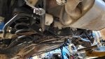
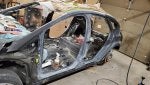
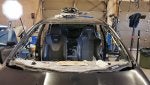
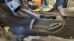
I really want to get the dashboard in to clear up some space, and hang all the loose wires. However, before that I have to deal with something. I have never felt comfortable with the whole driver's position in this car. The pedals are too high, steering won't go low enough, handbrake is buried down in a hole, and seats at odd angles. I didn't want to mess with such things on the '18 because that was a new car, and not even paid off yet. But this one.... well this one I feel pretty free to get into for some reason 😅

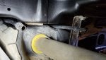
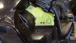
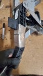
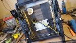
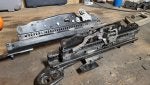
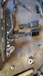
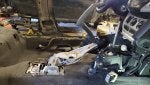
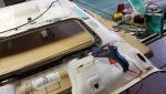
The first thing is the steering column. I was going to modify the SE one in case I made a mistake, but as you can see they are not totally the same. The RS one has a longer final section, possibly because of the lowered subframe and rack. Fortunately I found little modification was necessary. I just ovaled the front holes a little, and bent up the rear mounts on the dash beam, this gave me a suitable drop in height. Idk who could ever use this wheel at the normal full upwards adjustment, it's like a bus.

I imagine I'm somewhat alone in my assessment of the steering setup, but one thing I know I've heard complaints of (and there is a product to address it) is the pedals. The clutch and brake are soooooo high. The found solution of moving the accelerator up as well is not ideal for me, I'd rather move the others down.

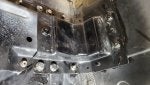
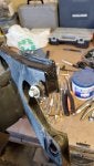
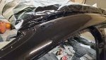
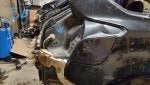
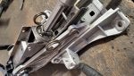
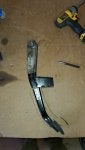
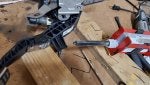
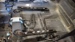
There is no adjustment in either pedal, as is normally found on most Japanese cars. On a Subaru or Evo this is as simple as turning a lock nut. Here we have to get crazy. As the brake switch and master cylinder link is also non adjustable, I decided the best way to move the pedal is to do it below that whole situation. Then I cut a wedge out of the brake pedal.

I know this looks a bit scary to some, but it is very solid steel, easy to weld back and add some reinforcement. Using a template, I moved it down about 3cm. This puts it about 1cm above the gas pedal at rest. Closed up the gap, welded it back together, and all is good. I had considered using a hinge and bolt combo to make it freely adjustable in the future, but no point really. Once it's set up for me it's unlikely to need changing.

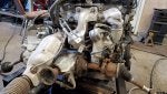
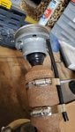
Now that was fairly easy, cut, weld, done. The clutch however is a different story. It's made of plastic and has 3 different sensors. If I changed the distance from the pedal to the master cylinder it would create a multitude of side effects. So, same solution I suppose. Cut a wedge.

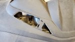
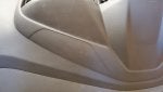
Using a torch I got the gap to close up and stay as such for fitting. Now of course that wouldn't fly in the long run. It needs to be reinforced. And we happend to have a compound on hand from earlier that would do the job.

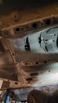
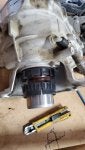
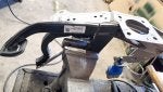
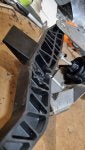
First, I made a metal skin to fit around the pedal and add reinforcement, as well as containment. Then cut channels into the latticework to allow flow and connection. Then, I filled the open space with panel bond. It's like cold weld, or other 2 part epoxies. The epoxy provides strength against compression, and the metal skin prevents expansion. In the end, I think this pedal is stronger than it was at the start.

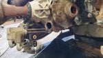
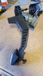
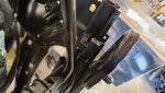
Also added an adjustable stopper for the base to set the clutch release point. Having it right on the pedal backing will prevent any additional stress to the arm.

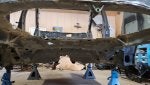
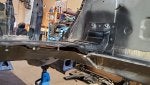
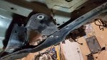
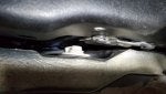
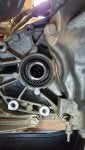
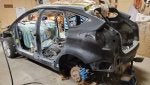
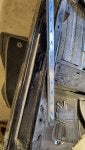
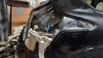
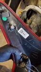
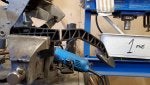
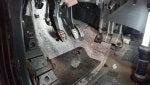
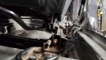
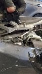
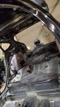
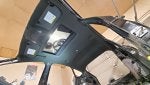
When putting the completed assemblies in, I discovered this heavy tab on the dash beam. It severely blocks ingress of the clutch assembly and doesn't appear to provide any purpose aside from keeping the clutch system from moving right in the event of an accident that causes firewall movement. Given the clutch is plastic anyway, I deemed it annoying and cut it off. I'm not sure if anyone has tried to take the clutch assembly out with the dashboard in place, but I think this tab might necessitate removal.

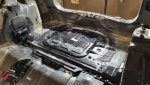
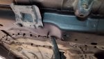
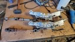
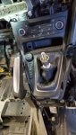
And that's it! All pedal in a nice normal row now. Easy to switch between, and more precise actuation.
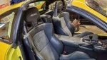
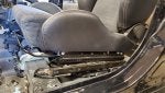
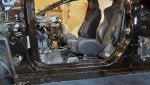
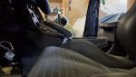
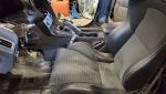
Next, seats.
 

Attachments

#49 ·
Evo X or Ralliart Recaro seats are pretty much my favorite North American market seats from any car. Look good, feel good, heated and easy to get your hands on. They also have a symmetrical rail system that's easy to work with. How to make them fit with the Focus' much more oem style seat system took a bit of trial and error.

First, I tried to see if I could just put them in place, maybe drill some new holes, and be done with it using the complete Mitsubishi mounting system. There were several problems with this. Rails were too short to reach the rear mounts, all mounts were in rather different places, also the rail feet made them sit very out of line with the steering wheel. The Lancia Stratos might be a fantastic car but I really don't want to recreate that awful driving position.

So I thought ok, I'll cut off the rail feet from the Focus seats, and weld them onto the Evo seats. But this also presented problems, namely that the rails were still too short on the inboard side. Then I discovered both seat rails were the same distance apart give or take a few millimeters. If I were to cut off the whole rail system on the Focus, bolt them to the floor, and put the Evo rails on top, it might just work. I hacked up the SE seats for this, but the RS seats would be about the same process.

I set to removing the feet from the Evo seats which left a smooth flat surface. Then I removed all the rivets and brackets from the Focus rails which also left a smooth flat surface. I suspected it might be too high, but placing one set of rails onto the other the height was exactly right for me.

I moved the power seat track into a neutral center position before removing the rest of the mechanism. To set the lateral position I first put the rails centered on one another. This still resulted in an uncentered driver to wheel situation, so I fiddled with it until things were right on. This resulted in an offset mounting with the Evo rail halfway centered on the Focus rail.

With that, the basic seat mounting was complete. As you can see, they sit slightly lower than the regular RS seat and at a more reasonable angle. If you wanted them lower yet, you could lose an inch or so by cutting the lower Focus rails to the base plate and welding to that instead.

I replicated this on the passenger side, but put the lateral position exactly centered to give more space against the center console.

Next time I'll figure out seat belts, then airbags, heaters, and sensors.
 

Attachments

#50 ·
Very nice job with the seats! I will be watching closely at how you proceed with wiring next as this is where I stopped planning this swap when I was looking at this option.

It seemed the airbags didnt have the same resistance between the Evo and Focus but perhaps a resistance can be added or the system might just also take it as is...otherwise heated seats should be straight forward! Also curious to find out how you will mount/defeat the passenger seat occupancy sensor/bladder.

There is a clean set of evo seats for sale locally which I could most likely buy for 1000$cad + a set of junkyard focus rails so I dont hack the stock seats...you might have just revived this idea in my mind!

Your rebuild thread is awesome thanks for sharing it step by step!
 
#51 ·
I love seeing how things get put together on these cars and what lies underneath the surface. Lots of hard work you're doing; thanks for all the pictures!
 
#52 ·
From what I read, the airbag resistance should be similar within an ohm, and I'm hoping the system is not that picky. I need to get the rest of the car wiring finished, and the dashboard in before I can start testing all the seat accessories. If it is required higher, I can add a resistor.

For the bladder, I believe I can just slide it under the Evo cushion in a similar fashion to the Focus seat. Two things to deal with today though, the seatbelts, and the seat position sensors.

As you can see, the Evo seatbelt buckle is quite a bit shorter, which means the mounting point is higher. Using the Focus buckle on this point works, but it makes the buckle rub on your hip, and especially in a crash I think it would feel a bit painful. So using the large nut/washer from the Focus seat, I lowered the mounting point as far as possible. Ideally lower would be better, but this works.

The seat position sensors let the SRS system know when the seat has been moved up extremely close to the dash by providing a magnetic signal as it goes along the rail. When you push a seat far forward, the sensor goes past the rail, losing the signal. I experimented with many different ways to incorporate this into my seats yet the different design precluded any easy answer. The Evo seats have these as well, but operation is inverse - no mag signal means normal position.

I measured the the distance to the base of the backrest on the Focus seats at which point this sensor trips, and adjusted the Evo seats to the same position. I found it to be further forward than any normal situation would require, and further than my 5'1" wife would need to put it. Therefore, I instead decided to put the sensors in a fixed position, and limit the rail adjustment to not exceed this point.

A ball of weld along the adjuster track now stops the seat before it exceeds the maximum airbag distance. There is a way you could engineer the sensors to work normally, but unless you are extremely short, and have lowered pedals like I do, it's unlikely you'll ever need to breach the limit.

Also the RS shell has been dragged outside. I'm surprised how light it is.
 

Attachments

#55 · (Edited)
Cars get picked clean out there eh? Things we only see in movies.

This next bit with the dashboard is really unnecessary, unless the RS dash is scratched up by a million glass shards like mine, or maybe airbags blown. The SE didn't have nav, or a gauge pack so that adds to the work here.

Cutting a great big hole in the center of the dash didn't feel great, fortunately it has the area basically marked out. Using a step drill bit and a dremel it was easy enough to cut.

Adding the push start button went much smoother. Just a hole saw and some fine trimming. The sunlight sensor in the top center of the dash needed to be swapped out too, but no modifications neccessary.

Aside from that, this pre facelift dash appeared to be otherwise no different than the more recent version. Not until I tried to add the shifter console did I find more quirks. The lower section of the two is again incompatible, but it's not hard to remedy. The new dash is essentially just a cut up version of the old one. So you can use an old dash on a new car, but not the other way around. I just trimmed the second row of tabs, and enlarged the outer rim. I also found a missing tab hole on the right side, and again it was correspondingly marked to be drilled out.

Dash airbag for the passenger swapped out without issue, as did all the wiring and side vents. Felt good to finally have that thing off the ground and put in place.

And now that I have a dash, and something to aim at, I'm going to find a way to make that huge, elegant parking brake work. Note this picture was from the initial disassembly, certainly not using those HVAC controls.
 

Attachments

#56 ·
I'm curious if any of you have the same assessment of the standard RS handbrake being far too small and low to operate while driving. It is probably the worst positioned handbrake (aside from an old Toyota truck) that I've experienced. Making the large SE one fit will be a challenge.

In the bolt in position, it does fit but sits too low against the console. Hard to get your hand around in a quick motion. So the first change will be to raise the lower stopping point. The next picture has it at one notch up and is better to grip.

I tapped a hole an made an adjustable stopper which will likely need to be changed slightly after driving it to make sure it's not dragging. Currently I can get a maximum of 7 clicks which is about right for range of motion. I also added a screw spacer to the brake switch so it would recognize the new position as down.

The very different console designs from the interior facelift mean there will be some plastic cutting neccessary. First, I had to cut a slit just in front of the brake to allow the console to even be installed. A backing plate and screws help it stay rigid and removable. A number of other tabs and edges had to be removed as well. As for the original brake boot, it is cleary in a different area code.

The only way I could make this work, and still look good was to have the brake boot panel lift with the brake when it's pulled, and lower when released. With the seat in place it will look ok. A few heavy o rings make it stay with the panel and move up and down. As for the original boot, I tied off the hole where the brake use to poke through, inverted it, and now it's a storage pocket.

One thing that was hard to document was all the small modifications I had to make to both the brake lever, and the console to allow a full range of motion. For 5 clicks it fit mostly ok, but once you get into 6-8 it fouls on many parts and tries to lift the console with it. I made it work, it just took literally all day.

With the seat in place, the brake is now in a much better position. It's like a mechanical drift stick, quick and smooth to reach from wheel or shifter. The lever had a plastic cover but I gotta say the latticed aluminum looks good, so I just left it off.
 

Attachments

#57 ·
I'm curious if any of you have the same assessment of the standard RS handbrake being far too small and low to operate while driving. It is probably the worst positioned handbrake (aside from an old Toyota truck) that I've experienced. Making the large SE one fit will be a challenge.
I totally agree on that. Mine is way too close in with the cupholder. I do have a little 3d printed phone holder there but still....
 
#58 ·
Uninteresting items first, curtain airbags, finalize wiring, and miscellaneous roof items. This is because it's time to make a new headliner!

The black RS one was clearly damaged from the roof collapse, while the SE one is fine, but white. My first thought was the graft the front shell section of the white one onto the black one and lay the fabric over it. However when pulling the fabric back, a good amount of the hard backing came with it. This both meant a significant amount of the structure was lost, and the fabric still retained many wrinkles. Further separating it made it too thin to use.

Fortunately I found a great upholstery supply while rebuilding an MGB last year, and they had a very good match for the RS material. I picked charcoal black.

I always forget how useful a glue gun is, in my mind it's a 1990s relic. This secured the sunroof border, and wiring to the top. A contact adhesive spray was used for the actual fabric.

Due to the foam backing, it is very hard to get it to follow the contours of the front around the visors and console. Heat had little effect on test pieces, but did create smoke and melting. I did the best I could, and honestly it looks pretty good to me. Especially since the wrinkled areas will be covered by the visors anyway.

Once fitted in the car, it actually smoothed out even more, so great! Been waiting to deal with that for a while, good it's done.
 

Attachments

#61 ·
@HiluxSR5
Had you thought about doing a starlight headliner while you had it out? I always thought they looked kinda cool.
More weight < Shiny lights +5Hp
[emoji38]
That would be cool! Rolls meets RS... Could add massage chairs and chilled champagne storage while you’re at it..